


ATV KIT - ATV Plow Mount Plate
| Product: | ATV |
| Project no: |
487803673_rev1
|
| Instruction Sheet P/N: | 487803673 |
| Revision no: |
1
|
| Revision date: |
October, 2022
|
| Item covered: | ATV Plow Mount Plate |
The following symbols may be used in this document:
Indicates a hazardous situation which, if not avoided, could result in death or serious injury.
NOTICE Indicates an instruction which, if not followed, could severely damage vehicle components or other property.
- For safety reasons, this kit must be installed by an authorized BRP dealer.
- This kit is designed for specific applicable models only (authorized BRP dealers will confirm model(s)). It is not recommended for units other than the one (those) for which it was sold.
- If the installation of the kit requires a template, ensure template is to scale.
- Should removal of a locking device (e.g. lock tabs, self-locking fasteners, etc.) be required when undergoing disassembly/ assembly, always replace with a new one.
- Torque wrench tightening specifications must strictly be adhered to.
- Always wear EYE PROTECTION AND APPROPRIATE GLOVES when using power tools.
- Unless otherwise specified, engine must be OFF when performing any operation on the vehicle.
- Always be aware of parts that can move, such as wheels, transmission components, etc.
- Some components may be HOT. Always wait for engine to cool down before performing work.
Some important safety information and/or operating instructions dedicated to the end user might be included in this instruction sheet. Make sure to give the kit part number as well as the instruction sheet included with this kit to the customer. Verify that the customer has access to all the information required for proper use of the accessory.
NOTE: USE TIGHTENING TORQUES IN THE FOLLOWING TABLE IF NOT OTHERWISE SPECIFIED.
| GRADE | ||||
| 5.8 | 8.8 | 10.9 | 12.9 | |
| M4 | 1.8 ± 0.2 N•m (16 ± 2 lbf•in) | 2.8 ± 0.2 N•m (25 ± 2 lbf•in) | 3.8 ± 0.2 N•m (34 ± 2 lbf•in) | 4.5 ± 0.5 N•m (40 ± 4 lbf•in) |
| M5 | 3.3 ± 0.2 N•m (29 ± 2 lbf•in) | 5 ± 0.5 N•m (44 ± 4 lbf•in) | 7.8 ± 0.7 N•m (69 ± 6 lbf•in) | 9 ± 1 N•m (80 ± 9 lbf•in) |
| M6 | 7.5 ± 1 N•m (66 ± 9 lbf•in) | 10 ± 2 N•m (89 ± 18 lbf•in) | 12.8 ± 2.2 N•m (113 ± 19 lbf•in) | 16 ± 2 N•m (142 ± 18 lbf•in) |
| M8 | 15.3 ± 1.7 N•m (135 ± 15 lbf•in) | 24.5 ± 3.5 N•m (18 ± 3 lbf•ft) | 31.5 ± 3.5 N•m (23 ± 3 lbf•ft) | 40 ± 5 N•m (30 ± 4 lbf•ft) |
| M10 | 29 ± 3 N•m (21 ± 2 lbf•ft) | 48 ± 6 N•m (35 ± 4 lbf•ft) | 61 ± 9 N•m (45 ± 7 lbf•ft) | 73 ± 7 N•m (54 ± 5 lbf•ft) |
| M12 | 52 ± 6 N•m (38 ± 4 lbf•ft) | 85 ± 10 N•m (63 ± 7 lbf•ft) | 105 ± 15 N•m (77 ± 11 lbf•ft) | 128 ± 17 N•m (94 ± 13 lbf•ft) |
| M14 | 85 ± 10 N•m (63 ± 7 lbf•ft) | 135 ± 15 N•m (100 ± 11 lbf•ft) | 170 ± 20 N•m (125 ± 15 lbf•ft) | 200 ± 25 N•m (148 ± 18 lbf•ft) |
| M16 | 126 ± 14 N•m (93 ± 10 lbf•ft) | 205 ± 25 N•m (151 ± 18 lbf•ft) | 255 ± 30 N•m (188 ± 22 lbf•ft) | 305 ± 35 N•m (225 ± 26 lbf•ft) |
| M18 | 170 ± 20 N•m (125 ± 15 lbf•ft) | 273 ± 32 N•m (201 ± 24 lbf•ft) | 330 ± 25 N•m (243 ± 18 lbf•ft) | 413 ± 47 N•m (305 ± 35 lbf•ft) |
The illustrations in this document show typical construction of the different assemblies and may not reproduce the full detail or exact shape of the parts; however, they represent parts that have the same or similar function.
Installation time is approximately 0.5 hour.
icon legend
| ICON | INDICATES |
|---|---|
|
|
Part kept for reinstallation |
|
|
Part to be discarded |
|
|
Hand tighten |
|
|
Do not tighten yet |
Required Tools
| REQUIRED TOOL | USE | ||
|---|---|---|---|
| T1 | Drill bit 7 mm (9/32 in) |
|
To drill hole in A-arm protector |
| T2 | Drill bit 12 mm (15/32 in) |
|
To drill hole in skid plate |
| T3 | Drill bit 22 mm (27/32 in) |
|
To drill hole in skid plate |
| T4 | Center punch |
|
To mark the holes to be drilled |
parts to be installed
| ITEM | DESCRIPTION | PART NUMBER | QTY |
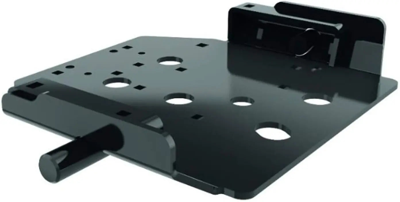
| P1 | Bottom Support | Not available separately | 1 |
| P2 | LH Attachment | 1 | |
| P3 | RH Attachment | 1 | |
| P4 | Hardware Kit (Includes P4a to P4e) | 715008098 | 1 |
| P4a | Spacer | Not available separately | 12 |
| P4b | M10 X 140 Hex. Bolt | 1 | |
| P4c | M10 X 50 Carriage Bolt | 4 | |
| P4d | M8 Flanged Nut | 2 | |
| P4e | M10 Flanged Nut | 5 | |
| P5 | Winch Cable Guide Kit (Includes P5a to P5d) | 705009222 | 1 |
| P5a | Cable Guide | Not available separately | 1 |
| P5b | M6 X 110 Socket Head Screw | 2 | |
| P5c | M6 Nut | 2 | |
| P5d | Cotter Pin | 1 |
instructions
NOTE: Some components were removed from illustrations for clarity purposes.
In the below illustrations, mostly LH side shown. Repeat for RH side if needed.
Please refer to appropriate online SERVICE MANUAL if needed.
Before installing the mounting plate:
- 1 - Determine if your vehicle is equipped with chassis protector (underbelly skid plate) or suspension arm guards. If this is the case, refer to the PREPARING A-ARMS AND SKID PLATES topic.
- 2 - Determine if your vehicle is equipped with the proper winch cable guide. If this is not the case, refer to: CHANGING THE WINCH CABLE GUIDE topic.
- 3 - Follow the installation steps for the mounting plate.
NOTE: If the vehicle is not new, make sure there is no dirt between the frame protector (underbelly skid plate) and the frame. It is IMPERATIVE to have a perfectly clean support surface between the frame and the protector. If in doubt, remove the guard, clean it and reinstall on vehicle.
vehicle preparation
Changing the Winch Cable Guide
1. Take the winch cable out about 1 m (3.3 ft).
2. Disconnect the battery.
NOTICE Always disconnect battery before doing any electrical installation. Always disconnect battery in this specified order, BLACK (–) cable first. Do not place tools on battery.
3. Remove the cable hook by removing the cotter pin and clevis pin.
typical - hook
1. Hook and Strap
2. Cotter Pin
3. Clevis Pin
4. Remove the hawse fairlead or roller fairlead from the vehicle. Discard screws and nuts.
Typical - hawse fairlead
1. Fairlead
2. Screw
3. Nut
5. Run the cable through the old or new roller fairlead and reinstall/install roller on vehicle. Secure the roller using the 2 new kept M8 x 20 socket head screw [P5a] and M6 nuts [P5b] at the back. Tighten to specification.
The kit provides a large roller that goes below the little one.
| Tightening Torque | |
|---|---|
| M8 x 20 Socket Head Screw [P5a] | 16 ± 2 N•m (142 ± 18 lbf•in) |
typical - roller fairlead
1. Cable
2. Roller Fairlead
3. M8 x 20 Socket Head Screw [P5a]
4. Large roller
6. Reinstall the hook on the cable. Use the clevis pin and the new cotter pin [P5c] to secure.
1. Hook
2. Clevis Pin
3. Cotter Pin [P5c]
4. Hook Strap
Preparing A-Arms and Skid Plates
Preparation time is approximately 0.4 hour for plastic triangular arm protectors.
Preparation time is approximately 0.6 hour for aluminum triangular arm protectors.
1. Using the appropriate workshop equipment and If the vehicle is equipped with A-arm protectors, lift the front of the vehicle safely. Lock the vehicle in this position. Remove the front wheels.
2. If the vehicle is equipped with A-arm protectors, refer to the “OPERATIONS CHART - A-arm protectors” to determine the type of protectors and the appropriate operations to be performed.
- If the vehicle has one of these A-arm protectors go to step 3.
- If the vehicle does not have any of these A-arm protectors, go directly to step 4.
3. Remove the protectors and attach the drilling template (with adhesive tape) on the protector using the markers illustrated according to the protector template. Then:
- Mark the holes to be drilled using a centre punch and a hammer.
- Mark the cuts to be made.
- Remove the drilling template.
- Perform the operations indicated in the operations chart.
NOTICE When drilling the skid plate, drill the indicated holes to the correct diameter
|
OPERATIONS CHART - A-arm protectors The left side is illustrated. Repeat the same instructions on the right side. |
||
|---|---|---|
| TYPE | MODEL / IMAGE / DESCRIPTION | OPERATIONS ON THE PROTECTOR |
| Protector 1 |
|
1. 715007751_TEMPLATE_5
2. Cutting line to perform 3. Hole to drill Ø 7mm (9/32'') |
NOTE: Use the new hole to reinstall the protector.
| Protector 2 |
|
1. 715007751_TEMPLATE_6
2. Cutting line to perform 3. Hole to drill Ø 7mm (9/32") [T3] 4. M6 Carriage bolt 5. Socket (not included) 6. Vice |
After drilling the 7 mm (9/32 in) hole, insert the carriage bolt into the hole. Use a long socket and tighten everything in the vice to notch the hole with the square base of the carriage bolt.
NOTE: Use the new hole to reinstall the protector.
| Protector 3 |
|
1. 715007751_TEMPLATE_7
2. Cutting line to perform |
| Protector 4 |
(Plastic)
|
1. 715007751_TEMPLATE_8
2. Cutting line to perform |
| Protector 5 |
(Aluminium)
|
This protector is not compatible. Remove the A-arm protectors from the vehicle |
| Protector 6 |
|
1. 715007751_TEMPLATE_9
2. cUTTING LINE TO PERFORM |
3mm Plastic Skid
Using the 715007751_TEMPLATE_1, make 4 marks on the skid for drilling.
Using the 22 mm (27/32 in) drill bit, drill 4 holes in skid plate.
Using the 715007751_TEMPLATE_4, cut the side of the skid.
5mm Aluminum Skid (Except Renegade X mr)
Using the 715007751_TEMPLATE_2, make 4 marks on the skid for drilling.
Using the 22 mm (27/32 in) drill bit, drill 4 holes in skid plate.
5mm Aluminum Skid (Renegade X mr)
Using the 715007751_TEMPLATE_10, make 4 marks on the skid for drilling.
Using the 22 mm (27/32 in) drill bit, drill 4 holes in skid plate.
6mm Plastic Skid
Using the 715007751_TEMPLATE_3, make 4 marks on the skid for drilling.
Using the 22 mm (27/32 in) drill bit, drill 4 holes in skid plate.
10mm Plastic Skid
Please refer to INSTALLING THE BOTTOM SUPPORT (6X6 10MM PLASTIC SKID PLATE) topic.
Mounting Plate - Spacer Chart
NOTE: It is important to use the proper amount of spacers. Please refer to the following chart.
| Skid Plate Set-up | Spacer Qty |
|---|---|
| Without Skid Plate | 0 |
| 3mm Thick - Production Skid Plate | 4 |
| 5mm Aluminum Skid Plate | 12 |
| 6mm Thick - Accessory Skid Plate | 12 |
| 10mm Thick - 6X6 Models Skid Plate | 4 |
Installing the Bottom Support (Except 6X6 10mm Plastic Skid Plate)
NOTE: If the vehicle is not new, make sure there is no dirt between the frame protector (underbelly skid plate) and the frame. It is IMPERATIVE to have a perfectly clean support surface between the frame and the protector. If in doubt, remove the guard, clean it and reinstall on vehicle.
1. Remove and discard the front differential support nut and bolt.
1. Front Diff. Support Bolt
2. Front Diff. Support Nut
2. Install LH attachment [P2] and RH attachment [P3] and secure using the new M10 X 140 hex. bolt [P4b] and a new M10 flanged nut [P4e]. Hand tighten only.
LH attachment view
1. LH Attachment [P2]
2. New M10 Flanged Nut [P4e]
3. New M10 X 140 Hex. Bolt [P4b]
RH attachment view
1. RH Attachment [P3]
2. M10 X 140 Hex. Bolt [P4b]
3. If you need to add some spacers [P4a]: make sure to put them into the right positionning.
NOTE: Spacers needs to be insert between the bottom support and the LH and RH attachments.
NOTE: It is important to use the proper amount of spacers. Please refer to the following chart.
| Skid plate set-up | Spacer Qty |
|---|---|
| Without Skid Plate | 0 |
| 3mm Thick - Production Skid Plate | 4 |
| 5mm Aluminum Skid Plate | 12 |
| 6mm Thick - Accessory Skid Plate | 12 |
| 10mm Thick - 6X6 Models Skid Plate | 4 |
typical - 1 spacer set-up
1. Spacer [P4a]
typical - 3 spacers set-up
1. Spacer [P4a]
4. Install and secure the bottom support [P1] using 4 M10 X 50 carriage bolts [P4c] and 4 M10 flanged nuts [P4e]. Hand tighten only.
1. Bottom Support [P1]
2. M10 X 50 Carriage Bolt [P4c]
1. M10 Flanged Nut [P4e]
5. Make sure the mounting plate rods are passing through the frame holes.
6. Push the bottom support back to the rear until it no further moves. Tighten to specification.
| Tightening Torque | |
|---|---|
| M10 Flanged Nut [P4e] (qty 5) | 48 ± 6 N•m (35 ± 4 lbf•ft) |
7. Tighten the front differential nut.
1. Front Diff. Support Bolt
2. Front Diff. Support Nut
| Tightening Torque | |
|---|---|
| Front differential nut | 48 ± 6 N•m (35 ± 4 lbf•ft) |
Installing the Bottom Support (6X6 10mm Plastic Skid Plate)
NOTE: If the vehicle is not new, make sure there is no dirt between the frame protector (underbelly skid plate) and the frame. It is IMPERATIVE to have a perfectly clean support surface between the frame and the protector. If in doubt, remove the guard, clean it and reinstall on vehicle.
1. Remove the skid plate. Keep the skid plate, all hardware and the front bracket to be retained for subsequent use.
1. Skid Plate
2. Hardware
3. Front Bracket
2. Remove and discard the front differential support nut and bolt.
1. Front Diff. Support Bolt
2. Front Diff. Support Nut
3. Install both of the mounting plate brackets and secure using a new M10 X 140 hex. bolt [P4b] and 1 new M10 flanged nut [P4e]. Hand tighten only.
LH attachment view
1. LH Attachment [P2]
2. New M10 Flanged Nut [P4e]
3. New M10 X 140 Hex. Bolt [P4b]
RH attachment view
1. RH Attachment [P3]
2. New M10 X 140 Hex. Bolt [P4b]
4. Install the bottom support using the 4 M10 X 50 carriage bolt [P4c], 4 spacers [P4a] and secure using 4 M10 flanged nut [P4e]. Tighten to specification.
| Tightening Torque | |
|---|---|
| M10 Flanged Nut [P4e] | 48 ± 6 N•m (35 ± 4 lbf•ft) |
typical - 1 spacer set-up
1. Spacer [P4a]
5. Temporarily reinstall the skid plate on top of the bottom support. Do not tighten yet.
6. Use the bottom support as a template, make 2 marks on the skid plate for drilling.
top view
7. Remove the skid plate and using the 12 mm (15/32 in) drill bit, drill holes in the skid plate.
8. Reinstall skid plate and using the previously removed M8 X 40 screws in new holes and secure with 2 new M8 flanged nut [P4d]. Do not tighten yet.
1. M8 X 40 Screw
2. M8 Flanged Nut [P4d]
9. Reinstall all the remaining previously removed hardware. Tighten to specification.
| Tightening Torque | |
|---|---|
| M8 x 40 Screw (qty 9) | 10 ± 0.5 N•m (89 ± 4 lbf•in) |
| M6 X 30 Screw (qty 8) | 4.5 ± 0.5 N•m (40 ± 4 lbf•in) |
1. M8 x 40 Screw
2. M6 X 30 Screw
Safety Label
This product comes with the following label containing important safety information.
The label should be considered a permanent part of this product. If the label comes off or becomes hard to read, please contact an authorized dealer for FREE OF CHARGE replacement.
Any person who intends to use this product should read and understand the information contained on the label before doing so.
Pinch Point. Keep Hands Away.
top view - winch roller fairlead
Templates.pdf